Here is one HDMI input issue you can troubleshoot without breaking the bank. Any time you use any type of transmission line there are losses over distance. It’s just the way it is. So, to combat this an installer must use the proper cable that can ensure the delivery of the video signal’s destination with enough integrity the receiving device requires. This dynamic range of signal integrity can vary from cable to cable or any device used within the system.
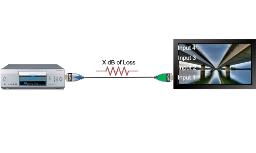
The illustrations detail how these variables become part of your system design. Fig. 1 depicts a basic system setup. No brainer here; output from the source is connected to the input of the sink (display). The installer picks HDMI 1 as its default input. That seems to be a reasonable thought process. Now look at Fig. 2. Inside the display usually holds a host of printed circuit boards.
Some may be a power supply and others can be video drivers depending on how the display is made. But there is always one board or part of a board that is designated as the “input board.” They do this so they can position the HDMI connectors on the chassis so they are easily found and connected with the least amount of visibility.
Now look closely at the simulated traces in Fig 2. All the inputs have different colors for ease of recognition. The HDMI chip in this case has its inputs on all four sides. Some may come with two per side, or three on one side and two more on the other side. The reason why they don’t set these up to be on one side is due to the eight video lanes required for each input. These chips are small and many times the pins are positioned around the perimeter of the part.
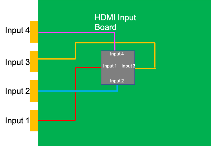
Out of all the inputs, which is the best to use — 1, 2, 3, or 4? The answer is #2, it has the shortest distance to the part. These traces have losses just like your cables and sometimes if you are using products that have a bit low output and unknown cable performance, you could be low in its minimum input threshold and at a make-or-break operation. How do you determine the best input to use?
The way that we do this in the lab is with a variable out control on our signal generators. They are designed to do this. Clearly, something you don’t want to bang around a truck or out in the field. So by varying the output of the generator, we could determine what input is the most sensitive. Just lowering the output until an image is lost tells you the story.
But what about doing this at a job? To do this is very easy. Just get a known source. Apple TV, Blu-ray player, or any source device. Now you take a sampling of HDMI cables at different lengths and quality and begin to troubleshoot by substituting each cable in one input at a time. You just have to make sure you have at least one cable that fails (and in the HDMI world that’s pretty easy).
The longer you go, the more loss there is in the cable. When you finally get to where the signal cuts out or the display starts to sparkle, you are at the low threshold limit of that input. Then all you do is take that same cable that did not make it and try it in the remaining inputs. If your cable selection consists of some uniformed cables with losses, you will find the “sweet spot” of each display … and the best input for you. You don’t have to stick with that last test cable for sure. Just select one that has the rating you need and length and you are done. This has worked for me many times I’ve been in the field with no test equipment.
This is good practice for any system. Troubleshooting an HDMI input in this way could save you a truck roll on those systems that are just too close for comfort!


