Last month we addressed performing emissions testing on HDMI cables when they start getting over the 6Gbps range of throughput. These signals radiate outwards from the cable and if emission levels are excessive, they can raise a tremendous number of anomalies.
But what happens within the copper or fiber cable assembly itself? In fact, in some fiber products, emissions can be even harder to control due to the active devices within each head shell.
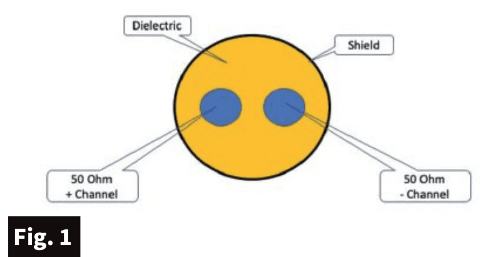
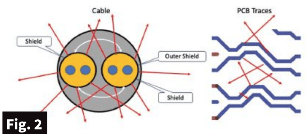
Fig. 1 demonstrates a typical differential channel inside each copper digital video cable. No big shakes here; two identical 50-ohm wires surrounded by some form of shield. They can be found in Twin-Ax or twisted pair configuration. With correctly designed shields, both can do a very good job keeping noise and radiated emissions from leaking out.
Fig. 2 shows what happens when two differential pairs are placed within one jacket or in fibers using differential traces on the PCB within the shells. We’re looking at not only the entire assembly but between each differential channel.
If noise, or signal in this case, is high it will interfere with the adjacent channel. This is very similar to crosstalk where one channel can be the aggressor and the other the victim. Crosstalk can be viewed as a form of emissions via the signals being generated within the cable — Transmission Minimized Differential Signaling for v2.0 and Fixed Rate Link for v2.1.
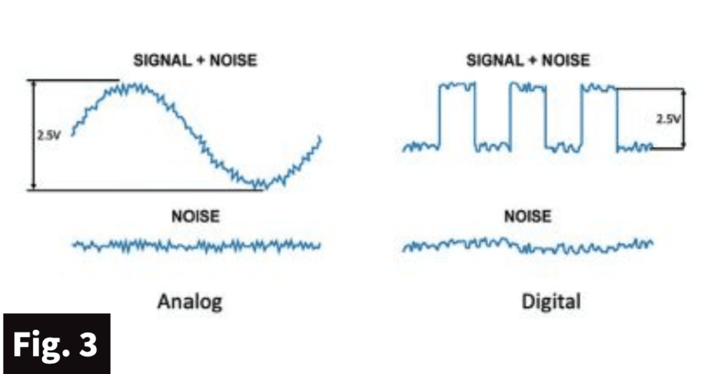
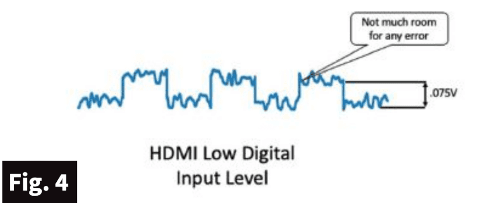
Fig. 3 shows what analog and digital signals looks like with noise. It’s not as much of a problem with digital as it is with analog. But with HDMI’s new revision calling for 12Gbps over each channel, it gets a bit dodgy. Typical digital signals can have a peak-to-peak dynamic of as much as 5 volts (Fig. 4). Typical analog has always been less with only 2.5 volts. Digital signaling has far less of a noise problem than analog, until you get to HDMI’s new revision. Now the input sensitivity level limit drops to an all-time low of just 100mv or .1 volts peak to peak, which can happen over longer lengths.
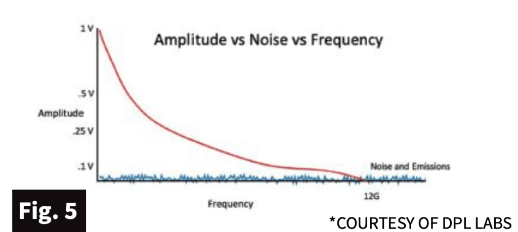
Do you see where I am going? With this low level of usable video signals, it’s a short walk to hit the 100mv over longer lengths with high-frequency content. A signal that leaves a source product can be as high as 1 volt (Fig. 5), offering major differences between the noise floor and the signal. But as it gets higher in frequency, this voltage level deteriorates due to insertion loss. It eventually will drop below the 100mv limit and mixes with the noise component. All it takes is some crosstalk or internal emissions to spoil the signal for any channel.
This is where the attenuation-to-crosstalk ratio needs attention. What makes matters worse is when the noise is just enough to influence an error intermittently. Having thin thresholds in either direction can vary by bends, turns or even atmospheric conditions when getting to the edge of breach.
These intermittent problems create sleepless nights. And there’s already a huge quantity of products in the field that have not been tested for radiated emissions. We’ll keep you posted.

